Step 5: Enhancing Tank State Display by Subscribing to Sensor Information Topics
In Step 5, we’ll create a program that subscribes to and utilizes sensor information topics.
Overview
In Step 4, we implemented functionality to output the Tank robot’s acceleration sensor and rate gyro states as sensor_msgs/Imu ROS topics. By subscribing to these topics, you can obtain sensor states via the network and utilize them in various processes. In Step 5, we’ll demonstrate this by having the state visualization Choreonoid node from Step 3 subscribe to sensor information topics, enhancing the Tank’s state display.
Sensor State Acquisition Controller
First, we’ll implement functionality to subscribe to sensor information topics in the state visualization Choreonoid node. We can achieve this using a simple controller, similar to the joint state visualization introduced in Step 3. Here’s the source code:
  1#include <cnoid/SimpleController>
  2#include <cnoid/BodyItem>
  3#include <cnoid/AccelerationSensor>
  4#include <cnoid/RateGyroSensor>
  5#include <cnoid/LazyCaller>
  6#include <cnoid/Timer>
  7#include <ros/node_handle.h>
  8#include <sensor_msgs/Imu.h>
  9#include <random>
 10
 11using namespace std;
 12using namespace cnoid;
 13
 14class RttImuStateSubscriber : public SimpleController
 15{
 16    unique_ptr<ros::NodeHandle> node;
 17    ros::Subscriber subscriber;
 18    BodyItemPtr bodyItem;
 19    AccelerationSensorPtr accelSensor;
 20    RateGyroSensorPtr gyro;
 21    Timer bodyShakeTimer;
 22    double bodyShakeDuration;
 23    Isometry3 bodyPosition;
 24    mt19937 mt;
 25    uniform_real_distribution<> rand;
 26
 27public:
 28    virtual bool configure(SimpleControllerConfig* config) override
 29    {
 30        bodyItem = static_cast<BodyItem*>(config->bodyItem());
 31
 32        auto body = bodyItem->body();
 33
 34        accelSensor = body->findDevice<AccelerationSensor>();
 35        if(accelSensor){
 36            auto sigTimeout = bodyShakeTimer.sigTimeout();
 37            if(!sigTimeout.hasConnections()){
 38                sigTimeout.connect([this](){ onBodyShakeTimerTimeout(); });
 39                bodyShakeTimer.setInterval(20);
 40            }
 41        }
 42
 43        gyro = body->findDevice<RateGyroSensor>();
 44
 45        node.reset(new ros::NodeHandle(bodyItem->name()));
 46        subscriber = node->subscribe(
 47            string("/") + bodyItem->name() + "/imu",
 48            1,
 49            &RttImuStateSubscriber::imuStateCallback, this);
 50
 51        return true;
 52    }
 53
 54    void imuStateCallback(const sensor_msgs::Imu& state)
 55    {
 56        callLater([this, state](){ updateImuState(state); });
 57    }
 58
 59    void updateImuState(const sensor_msgs::Imu& state)
 60    {
 61        if(accelSensor){
 62            auto& dv = state.linear_acceleration;
 63            accelSensor->dv() << dv.x, dv.y, dv.z;
 64            accelSensor->notifyStateChange();
 65            if(accelSensor->dv().head<2>().norm() > 20.0){
 66                startBodyShake();
 67            }
 68        }
 69        if(gyro){
 70            auto& w = state.angular_velocity;
 71            gyro->w() << w.x, w.y, w.z;
 72            gyro->notifyStateChange();
 73        }
 74    }
 75
 76    void startBodyShake()
 77    {
 78        bodyShakeDuration = 0.5;
 79        if(!bodyShakeTimer.isActive()){
 80            bodyPosition = bodyItem->body()->rootLink()->position();
 81            rand.param(uniform_real_distribution<>::param_type(-0.02, 0.02));
 82            bodyShakeTimer.start();
 83        }
 84    }
 85
 86    void onBodyShakeTimerTimeout()
 87    {
 88        if(bodyShakeDuration > 0.0){
 89            auto T = bodyPosition;
 90            T.translation() += Vector3(rand(mt), rand(mt), rand(mt));
 91            bodyItem->body()->rootLink()->setPosition(T);
 92        } else {
 93            bodyShakeTimer.stop();
 94            bodyItem->body()->rootLink()->setPosition(bodyPosition);
 95        }
 96        bodyItem->notifyKinematicStateChange();
 97        bodyShakeDuration -= 0.02;
 98    }
 99
100    virtual void unconfigure() override
101    {
102        node.reset();
103        subscriber = ros::Subscriber();
104        bodyItem.reset();
105        accelSensor.reset();
106        gyro.reset();
107        bodyShakeTimer.stop();
108    }
109};
110
111CNOID_IMPLEMENT_SIMPLE_CONTROLLER_FACTORY(RttImuStateSubscriber)
Create this source code in the src directory as “RttImuStateSubscriber.cpp” and build it by adding the following to CMakeLists.txt in the same directory:
choreonoid_add_simple_controller(RttImuStateSubscriber RttImuStateSubscriber.cpp)
target_link_libraries(RttImuStateSubscriber ${roscpp_LIBRARIES} Choreonoid::CnoidBodyPlugin)
You need to specify “Choreonoid::CnoidBodyPlugin” as a library to link for the same reason as in Step 3.
A successful build generates the simple controller binary file “RttImuStateSubscriber.so”.
Introducing the Sensor State Acquisition Controller
This controller is introduced to the state visualization Choreonoid node created in Step 3. It works in combination with the simulation Choreonoid node from Step 4.
First, copy the Step 3 project file “step3.cnoid” as “step5.cnoid” for this step.
Then create a launch file “step5.launch” to start both the simulation “step4.cnoid” and visualization projects together. The content should be:
<launch>
  <node pkg="choreonoid_joy" name="choreonoid_joy" type="node" />
  <node pkg="choreonoid_ros" name="choreonoid" type="choreonoid"
        args="$(find choreonoid_ros_tank_tutorial)/project/step4.cnoid --start-simulation" />
  <node pkg="rqt_graph" name="rqt_graph" type="rqt_graph" />
  <node pkg="choreonoid_ros" name="choreonoid2" type="choreonoid"
        args="$(find choreonoid_ros_tank_tutorial)/project/step5.cnoid" />
</launch>
After completing this work, the tutorial package has the following file structure:
+ choreonoid_ros_tank_tutorial
  - CMakeLists.txt
  - package.xml
  + launch
    - step1.launch
    - step2.launch
    - step3.launch
    - step4.launch
    - step5.launch
  + project
    - step1.cnoid
    - step2.cnoid
    - step3.cnoid
    - step4.cnoid
    - step5.cnoid
  + src
    - CMakeLists.txt
    - RttTankController.cpp
    - RttJointStatePublisher.cpp
    - RttJointStateSubscriber.cpp
    - RttImuStatePublisher.cpp
    - RttImuStateSubscriber.cpp
Launch the Step 5 launch file with:
roslaunch choreonoid_ros_tank_tutorial step5.launch
This displays main windows for both Choreonoid nodes. Each Choreonoid node’s project structure should be:
Choreonoid node for simulation (step4.cnoid)
+ World
  + Tank
    - RttTankController
    - RttJointStatePublisher
    - RttImuStatePublisher
  - Labo1
  - AISTSimulator
Choreonoid node for state visualization (step5.cnoid)
+ Tank
  - RttJointStateSubscriber
Introduce “RttImuStateSubscriber” to the state visualization Choreonoid node just as you introduced “RttJointStateSubscriber” in Step 3. Select Tank, create a SimpleController item from the main menu “File” - “New” - “SimpleController”, and specify “RttImuStateSubscriber.so” as its “Controller Module”. The item tree becomes:
+ Tank
  - RttJointStateSubscriber
  - RttImuStateSubscriber
Now the acceleration sensor and rate gyro states are reflected in the visualization Tank model. Save the project in the state visualization Choreonoid node to store this configuration in step5.cnoid.
Displaying Sensor State Values with Body State View
While sensor states are now reflected in the visualization Tank model, you cannot verify these states through this operation alone. The joint states targeted in Step 3 could be confirmed visually by reflecting joint angles in the model’s appearance. However, the sensors we’re working with only have internal state values that don’t directly affect the model’s appearance.
There are various ways to present sensor states. Let’s first display the sensor state values numerically. We can achieve this using the “Body State View” that Choreonoid provides as standard (through the Body plugin).
In the state visualization Choreonoid node, select “View” - “Show View” - “Body State” from the main menu. By default, this view appears in the area overlapping the message view at the bottom center of the main window. Move it to another area if needed for better visibility.
Here’s the state visualization Choreonoid node with this view displayed:
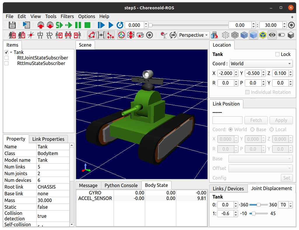
As shown, the Body State View displays state values for the Tank robot’s rate gyro “GYRO” and acceleration sensor “ACCEL_SENSOR”.
Try moving the Tank robot’s chassis using the gamepad. You’ll see the sensor values change. As in Verifying Output Topics from Step 4, turning the chassis and moving it forward/backward changes GYRO’s Z-axis component (third column in Body State View) and ACCEL_SENSOR’s X-axis component (first column), respectively. These changes are relatively easy to observe, so please verify them.
This demonstrates that “RttImuStateSubscriber”, the sensor state acquisition controller, successfully obtains sensor states. Internally, this works by subscribing to sensor states published by “RttImuStatePublisher” from the Tank robot being simulated in the simulation Choreonoid node.
Now that we’ve added the view, save the project so the Body State View displays on next startup. To save the view layout, ensure “Project File Options” - “Perspective” in the “File” menu is checked.
Collision Behavior
This sensor state acquisition controller includes a feature that presents robot collisions through animation, demonstrating practical use of obtained sensor information. This feature detects situations where large accelerations are applied to the robot as collisions, then randomly vibrates the visualization Tank model’s position for a set period.
Let’s test this feature. Using the gamepad, move the Tank robot in the simulation Choreonoid node and intentionally collide it with pipes or equipment in the environment model. The feature triggers more easily with higher-speed collisions. When a collision causes horizontal acceleration of 20 [m/s²] or more in the tank body, the feature activates and the visualization Tank model shakes as if it had collided.
Since we’re using a simple controller for sensor state acquisition, we can implement this kind of state presentation by adding processing to the controller. We’ll explain the implementation details later.
Introducing the Sensor Visualizer Item
As an additional way to present sensor information, let’s visually display the acceleration and angular velocity data in the scene view. Choreonoid provides the “Sensor Visualizer Item” as a standard feature (through the Body plugin) for this purpose.
Create a Sensor Visualizer Item from the main menu “File” - “New” - “SensorVisualizer”. This item functions by placing it as a child of the target body item. Select the Tank item in the item tree view when creating this item so it becomes a child of Tank. You can keep the default item name.
After introducing this item to the state visualization Choreonoid node, the item tree becomes:
+ Tank
  - RttJointStateSubscriber
  - RttImuStateSubscriber
  + SensorVisualizer
The Sensor Visualizer Item functions as a composite item, generating corresponding sub-items for each sensor in the target model. Expand the SensorVisualizer item in the item tree view to display its sub-items. The actual tree structure is:
+ Tank
  - RttJointStateSubscriber
  - RttImuStateSubscriber
  + SensorVisualizer
    - AccelerationSensor
    - RateGyro
    - Kinect-Image
    - Theta
    - Kinect-Image Theta
    - VLP-16
The displayed sub-items include acceleration sensor and rate gyro items first, followed by vision sensor items corresponding to each vision sensor mounted on the Tank robot. Checking each sub-item enables its visualization. However, since our controller doesn’t acquire vision sensor data, nothing displays even when these items are checked. We’ll cover vision sensor data visualization separately.
For this tutorial, we’ll visualize the acceleration sensor and rate gyro, so check the “AccelerationSensor” and “RateGyro” items. This visualizes current acceleration and angular velocity as arrow-shaped markers in the scene view.
Note that these markers overlap with the Tank model and become hidden inside it when values are small. To improve marker visibility, switch the scene view to wireframe rendering. Turn on the “Wireframe rendering” button in the scene view toolbar:

To further improve marker visibility, consider changing the scene view’s background color. Access this through the configuration dialog by clicking the settings button on the right side of the scene view toolbar. Click the “Background color” button in the dialog to open the color selection dialog and choose an appropriate color. White works well for this purpose.
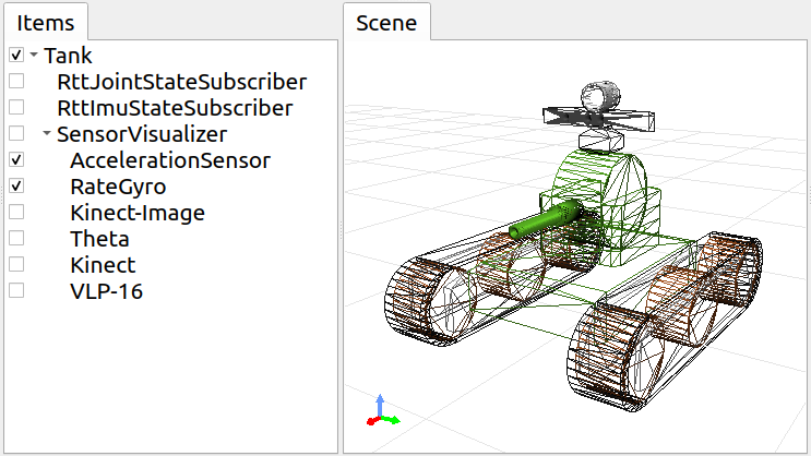
Here are the item tree view and scene view with these settings applied:
Now move the simulating Tank robot using the gamepad. You’ll see red and blue arrows appear in the scene view. Red represents acceleration, blue represents angular velocity. For example, when accelerating forward while turning left, the markers appear like this:
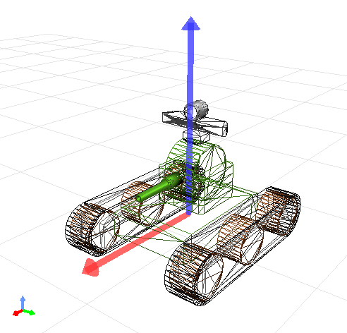
The red arrow’s direction and length correspond to acceleration’s direction and magnitude. Here you can instantly see that the robot is accelerating forward. The blue arrow shows angular velocity as a rotation vector. The arrow direction follows the right-hand rule for rotation, and its length represents the rotation’s angular velocity magnitude.
Note that acceleration visualization includes a default Z-axis offset corresponding to gravitational acceleration. This ensures the arrow marker length (acceleration magnitude) becomes zero when the accelerometer is stationary. This is configured in the AccelerationSensor item’s “Offset” property, which defaults to:
0.0 0.0 -9.8
These values correspond to the sensor’s local X, Y, and Z axes. The -9.8 offset on the Z axis cancels the gravity-measured acceleration component.
Sensor visualization sub-items have three visualization-related properties, including offset. Adjust these properties as needed for clearer sensor state display:
Display ratio
Sets the ratio between the sensor state vector magnitude and the marker length in the scene view.
Display threshold
Displays the marker only when the sensor state vector magnitude meets or exceeds this threshold.
Offset
Sets the offset vector described above.
Save the project after introducing the Sensor Visualizer Item to preserve this configuration in the project file.
Source Code Explanation
Let’s examine the source code of the RttImuStateSubscriber controller we introduced.
The basic source code structure matches RttJointStateSubscriber from Step 3. In RttJointStateSubscriber, the input was JointState topics containing joint displacements, and the update targets were the visualization body model’s joint displacements. In this controller, the input is Imu type topics containing angular velocity and acceleration, and the update targets are the visualization body model’s device objects. Additionally, this controller includes processing to vibrate the body model when detecting acceleration above a certain magnitude.
Header Includes
First, since we’re updating the acceleration sensor and rate gyro, we include their corresponding headers:
#include <cnoid/AccelerationSensor> #include <cnoid/RateGyroSensor>
We also include the Imu type header for the message type we’re subscribing to:
#include <sensor_msgs/Imu.h>
These are the same as Step 4, which uses the same data types and objects.
Additionally, we include headers for timers and random numbers used in the model vibration process:
#include <cnoid/Timer> …
#include <random>
The remaining headers are required for topic subscription, as in Step 3.
Member Variables
Let’s explain the new member variables introduced beyond Step 3’s controller. First:
AccelerationSensorPtr accelSensor; RateGyroSensorPtr gyro;
store the sensor objects to be updated.
Additionally, these variables are needed for the collision detection model vibration process:
Timer bodyShakeTimer; double bodyShakeDuration; Isometry3 bodyPosition; mt19937 mt; uniform_real_distribution<> rand;
We’ll explain these in detail later.
Initialization Process
The initialization process is implemented in the configure function, as in Step 3.
We obtain the acceleration sensor with:
accelSensor = body->findDevice<AccelerationSensor>();
If an acceleration sensor is found, we prepare for the model vibration process:
if(accelSensor){
    auto sigTimeout = bodyShakeTimer.sigTimeout();
    if(!sigTimeout.hasConnections()){
        sigTimeout.connect([this](){ onBodyShakeTimerTimeout(); });
        bodyShakeTimer.setInterval(20);
    }
}
bodyShakeTimer is a Timer type object. This extends Qt’s QTimer class to work with Choreonoid’s signal types. The sigTimeout used here is a signal emitted when the timer reaches its specified time interval. (This signal corresponds to QTimer’s original “timeout” signal.) We connect this signal to the onBodyShakeTimerTimeout function, which will be called on timeout. We set the timer interval to 20 milliseconds. This timer creates an animation showing model collision by vibrating the model at regular intervals.
Note that this initialization only needs to occur once after controller creation, so we skip it if already initialized. We check initialization status with:
if(!sigTimeout.hasConnections()){
    ...
}
This check is necessary because the configure function may be called multiple times when controller items are moved.
We also obtain the rate gyro:
gyro = body->findDevice<RateGyroSensor>();
We create a node handle and then create a subscriber:
node.reset(new ros::NodeHandle(bodyItem->name()));
subscriber = node->subscriber(
    string("/") + bodyItem->name() + "/imu",
    1,
    &RttImuStateSubscriber::imuStateCallback, this);
This process matches Step 3.
The topic name is “/(model name)/imu”, which becomes “/Tank/imu”. This matches the topic name published by the controller created in Step 4.
The callback function for topic subscription is:
void imuStateCallback(const sensor_msgs::Imu& state)
{
    callLater([this, state](){ updateImuState(state); });
}
This uses callLater to ultimately execute the updateImuState function from the main thread.
Updating Sensor Object States
The updateImuState function executes when topics are subscribed and updates the visualization model’s sensor object states:
- if(accelSensor){
auto& dv = state.linear_acceleration; accelSensor->dv() << dv.x, dv.y, dv.z; accelSensor->notifyStateChange(); …
If an acceleration sensor exists, we update its acceleration value with the subscribed value. After updating, we execute the sensor object’s notifyStateChange function to notify of this update. Update notification uses the sensor object’s sigStateChanged signal. The Body State View and Sensor Visualizer Item are connected to this signal and update their displays upon notification.
    ...

    if(accelSensor->dv().head<2>().norm() > 20.0){
        startBodyShake();
    }
}
If the horizontal (X, Y) acceleration vector magnitude exceeds 20.0 [m/s²], we assume the Tank robot has collided and start the visualization model shaking animation.
We apply the same update process to the rate gyro:
if(gyro){
    auto& w = state.angular_velocity;
    gyro->w() << w.x, w.y, w.z;
    gyro->notifyStateChange();
}
Unlike the acceleration sensor, there’s no additional processing here.
Model Vibration Animation
The model vibration animation starts by executing this function:
void startBodyShake()
{
    bodyShakeDuration = 0.5;
    if(!bodyShakeTimer.isActive()){
        bodyPosition = bodyItem->body()->rootLink()->position();
        rand.param(uniform_real_distribution<>::param_type(-0.02, 0.02));
        bodyShakeTimer.start();
    }
}
bodyShakeDuration is the animation duration, set to 0.5 seconds here.
Next, we check if the timer is running. If the timer’s isActive function returns true, the timer is active and animation is currently running, so we let it continue.
If isActive returns false, the timer isn’t running yet, so we execute the timer’s start function to activate it. At this point, we initialize bodyPosition (which stores the vibration center position) with the current model position, and also initialize the random number object used to determine relative vibration positions. The random number object is configured to return double values between -0.02 and 0.02.
void onBodyShakeTimerTimeout()
{
    ...
}
This function is called periodically by the animation timer and actually shakes the model:
if(bodyShakeDuration > 0.0){
    auto T = bodyPosition;
    T.translation() += Vector3(rand(mt), rand(mt), rand(mt));
    bodyItem->body()->rootLink()->setPosition(T);
} ...
During animation, we generate a position offset from the vibration center by random values for each X, Y, and Z axis, then update the model to that position. Repeating this every 20 milliseconds for 0.5 seconds creates the appearance of vibration.
    ...

} else {
    bodyShakeTimer.stop();
    bodyItem->body()->rootLink()->setPosition(bodyPosition);
}
When bodyShakeDuration reaches 0 or below, we end the animation. We stop the timer and restore the model to its original position (the vibration center).
bodyItem->notifyKinematicStateChange();
This notifies of the model update.
bodyShakeDuration -= 0.02;
This decreases the remaining animation time by the timer period. When this reaches 0 or below, the animation ends as described above.
Termination Processing
As in Step 3, we handle controller termination in the unconfigure function:
virtual void unconfigure() override
{
    node.reset();
    subscriber = ros::Subscriber();
    bodyItem.reset();
    accelSensor.reset();
    gyro.reset();
    bodyShakeTimer.stop();
}
This stops subscription, clears related object pointers, and stops the animation timer.