Displaying Sensor States
How to Check Sensor Values
When checking the state of a robot, you may want to check the state values of sensors mounted on the robot. Choreonoid provides the following functions for this purpose:
Body State View
Sensor Visualizer Item
These functions target body models loaded as body items in Choreonoid, referencing the sensor information stored there.
To apply these functions to simulation results, you need to enable Recording Device States so that sensor states during simulation are output to the body model. By doing this, you can easily display sensor states without modifying the robot’s controller. Additionally, to display cameras and range sensors, you need the Vision Simulator. You also need to enable Record vision data in the properties so that these results are also output to the body model.
Body State View
The “Body State View” is provided as a view that displays sensor state values directly as numerical values.
To use this, first display the view by selecting “Body State” from “View” - “Show View” in the main menu. By default, this view displays nothing. When you select a body item in the item tree view, it displays a list of sensor values that the body model has.
For example, when targeting the SR1 sample model, it displays as follows:
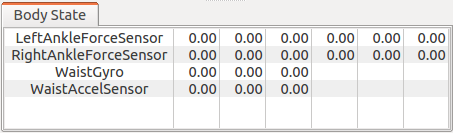
In the initial state, all values are 0 as shown in the figure, but the values change when you start a simulation. Also, when playing back recorded simulation results, the state at the target time is displayed.
Note that the sensor types currently displayed in this view are limited to force sensors, acceleration sensors, and rate gyro sensors.
Sensor Visualizer Item
The “Sensor Visualizer Item” is available as a function to visually display sensor states using 3DCG in the scene view. Using this, you can intuitively grasp the robot’s state.
To use this, first generate this item. As shown in the figure below, select “SensorVisualizer” from “File” - “New” in the main menu, and place the generated item as a child item of the target body item.
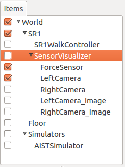
Then, the sensors that the body model has are arranged as child items of the sensor visualizer. Currently supported sensors are force sensors and cameras, range cameras, and range sensors from Vision Sensors. The sensor name is assigned as the item name. For range cameras, two items are generated: one for images (displayed with “_Image” appended to the sensor name) and one for range images.
By checking these child items, you can visualize the sensor data.
When visualizing force sensors, the model’s current sensor values are displayed as arrow markers in the scene view. Of the six-axis force/torque components that force sensors have, only the three-axis force components are visualized, displayed as arrow markers representing vectors from the force sensor position.
Below is an example of visualizing the force sensors mounted on both ankles in the SR1 walking sample.
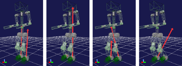
Here, the scene view is set to Wireframe Display to make the sensor visualization markers easier to see.
The length of the markers can be adjusted with the “display ratio” property of the sensor visualization item. Adjust this value according to the situation so that the markers are at a visible length.
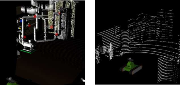
When visualizing range cameras and range sensors, they are displayed as point clouds in the scene view. Below are display examples from the sample project TankVisionSensors.