Vision Sensor Simulation
Vision Sensors
In Choreonoid, the following device types are defined as vision sensors:
Camera
RangeCamera
RangeSensor
Camera is a device corresponding to a video camera. It continuously acquires 2D image data at a constant frame rate.
RangeCamera is an extension of Camera that acquires not only 2D images but also the corresponding depth map (which stores the distance from the viewpoint to object surfaces in the image). An example of a sensor of this type is the Kinect.
RangeSensor is a device that assumes a 3D measurement device using lasers. It typically outputs one-dimensional distance data measured for one line. Some can output two-dimensional distance data similar to the depth map of RangeCamera.
These types of vision sensors are common sensors mounted on robots, and there is high demand for their simulation. Below, we explain how to simulate these sensors in Choreonoid.
Adding Vision Sensors
To use vision sensors, the sensors you want to use must first be defined as devices in the body model.
In Choreonoid model files (with extension .body), describe the sensors according to the Nodes for Defining Various Sensors and Devices specifications.
Vision Simulator
Vision sensor simulation functionality is usually implemented as a Sub-simulator and used in combination with a simulator item. Such subsimulators are called “vision simulators” in Choreonoid. The “GL Vision Simulator” is available as a standard vision simulator. This generates vision sensor data using the same rendering functionality used for drawing the scene view. Since this rendering functionality is implemented using an API called OpenGL, it is named GL Vision Simulator.
The vision simulator functions by placing it as a child item of the simulator item. When using the GL Vision Simulator, you can generate its item from the main menu “File” - “New” - “GL Vision Simulator”, and place it as a child item of the target simulator item.
By doing so, vision sensor simulation will also be performed for the virtual world targeted by the simulator item. Specifically, the image data of Camera devices, depth maps of RangeCamera, and distance data of RangeSensor will be updated at the frame rate set for each device.
GL Vision Simulator Settings
In addition to the basic settings for vision sensor simulation explained so far, you can configure detailed settings through the properties of the GL Vision Simulator item. The contents of each property related to settings are shown below.
Property |
Meaning |
|---|---|
Target bodies |
Specify by name the body models to be targeted for vision sensor simulation. Multiple models can be specified by separating with commas. If nothing is specified, all models are targeted. Set this item only when you want to limit the simulation target body models. Limiting target models may improve simulation speed. |
Target sensors |
Specify by name the vision sensors to simulate. Multiple sensors can be specified by separating with commas. Similar to “Target bodies”, set this item only when you want to limit the simulation target sensors. |
Max frame rate |
For all sensors, regardless of the sensor specification values, the frame rate set here becomes the maximum. Set this item when you want to improve simulation speed by reducing the frame rate. |
Max latency |
Sets the maximum time (latency) from when a sensor starts measurement until its result becomes available as data. For all sensors, regardless of sensor specifications, data becomes available after this time elapses. Reducing this value may slow down the simulation. |
Record vision data |
Sets whether to include vision sensor data such as camera images and distance data in Recording Device States for Recording Simulation Results. These data are generally large in size and consume a lot of memory even for short recordings, so they are usually not included. |
Use sensor threads |
In situations where multiple vision sensors are simulated, sets whether to assign a dedicated thread to each sensor. Usually keep this true, but depending on the number of sensors and the GPU being used, setting it to false may improve simulation speed. |
Best effort |
Vision sensors have a frame rate setting and are supposed to update data at intervals of that frame rate. When best effort is set to true, it allows updates to not be completed within that frame rate. The actual interval depends on the data generation processing inside the simulator. Conversely, when set to false, updates are performed according to the set frame rate. However, if the data generation processing does not finish within that time, it needs to wait for completion, which may slow down the simulation speed accordingly. Therefore, if improving simulation speed is more important than maintaining the frame rate, set this item to true. |
All scene objects |
Objects that can be displayed as 3DCG are called “scene objects”. For project items, those that are displayed in the scene view when checked in the item tree view are “scene objects”. This item sets whether to include scene objects other than body items in the virtual world visible to vision sensors. Scene objects other than body items include, for example, scene items. These do not affect the dynamic behavior in the simulation but can be used as visual elements of the virtual world. |
Range sensor precision ratio |
Range sensor distance data is generated using OpenGL’s depth buffer. This item sets the ratio of the depth buffer resolution to the range sensor resolution. Increasing the value improves the accuracy of distance data. |
Depth error |
Adds a constant offset to range sensor distance data. This item is still experimental, so please refrain from active use. |
Head light |
A light source that always illuminates from the viewpoint in the direction of the line of sight is called a “headlight”. This sets whether to enable this light source in camera image generation. |
Additional lights |
Light sources (lights) included in body models are called “additional lights”. This sets whether to enable these light sources in camera image generation. Set this to true if you want to simulate lights. |
Vision sensor simulation functions fully with the default settings, so it’s OK to set the above items only as needed.
Simulating Multiple Sensors
When the virtual world to be simulated contains multiple vision sensors, preparing one GL Vision Simulator item will simulate all of them by default. If you want to limit the sensors to simulate, set the “Target bodies” or “Target sensors” properties mentioned above.
There may be cases where you want to set the properties mentioned above independently for each sensor. For example, you might want to use best effort mode for cameras to minimize impact on simulation speed, but measure range sensors without dropping the frame rate. In such cases, prepare multiple GL Vision Simulator items, separate their “Target bodies” and “Target sensors”, and make the necessary settings for each. If both are placed as child items of the simulator item, they will be processed simultaneously during simulation.
Using Sensor Information
The simulated image data and distance data are stored internally in the simulator as data of the corresponding Device objects. By obtaining this data through some method, you can use the sensor data.
What actually uses sensor information is usually the robot’s controller. For controllers, each controller item specifies its own method for accessing devices, so obtain data for vision sensors according to that method. This is the same as for other sensors such as force sensors, rate gyros, and acceleration sensors. For actual access methods, refer to the manual for each controller item.
Example of Vision Sensor Usage
As an example of using vision sensors, we’ll introduce a sample that accesses cameras owned by a robot from a controller and outputs their image data to files.
Preparing the Robot Model
First, prepare a robot model that has Camera devices as the target robot model. As an example of such a model, we’ll use the SR1 model below.
In the SR1 model, vision sensors are defined as follows in its model file “SR1.body”:
-
  type: Camera
  name: LeftCamera
  translation: [ 0.15, 0.05, 0.15 ]
  rotation: [ [ 0, 1, 0, -90 ], [ 0, 0, 1, -90 ] ]
  id: 0
  format: COLOR
  nearClipDistance: 0.1
  elements: &CameraShape
    Transform:
      rotation: [ 1, 0, 0, 90 ]
      elements:
        Shape:
          geometry: { type: Cylinder, radius: 0.02, height: 0.025 }
          appearance:
            material: { diffuseColor: [ 1, 0, 0 ] }
-
  type: Camera
  name: RightCamera
  translation: [ 0.15, -0.05, 0.15 ]
  rotation: [ [ 0, 1, 0, -90 ], [ 0, 0, 1, -90 ] ]
  id: 1
  format: COLOR
  nearClipDistance: 0.1
  elements: *CameraShape
Here, nodes for two Camera devices corresponding to the robot’s left and right eyes are defined. Their format is “COLOR”, allowing them to acquire color camera images.
Creating a Simulation Project
Next, let’s create a simulation project for this model. As an example, we’ll use “SR1Liftup.cnoid”, one of the SR1 sample projects, as a base.
After loading the project, select “GL Vision Simulator” from the main menu “File” - “New” to generate a GL Vision Simulator item. The default name is “GLVisionSimulator”. Place it in the item tree view as follows:
In this way, place the GL Vision Simulator item as a child item of the simulator item. This enables the vision sensor simulation functionality by the GL Vision Simulator. When you run the simulation with this setting, the image data of the corresponding Device objects for the two cameras “LeftCamera” and “RightCamera” that the SR1 model has will be updated.
Sample Controller
We’ll use “CameraSampleController” as a sample controller that accesses camera images. This controller first displays a list of Camera devices that the robot has, and outputs their image data to files every second.
Note
The source for this controller is “sample/SimpleController/CameraSampleController.cpp”. If other SimpleController samples have been built, this sample should also be built.
Add this controller to the project. Similar to the examples in Creating a Controller Item and Setting the Controller Body, generate a “Simple Controller” item and arrange it as follows:
The name of the added controller item is “CameraSampleController” here.
Note that this item is placed as a child item of “SR1LiftupController”. By doing this, you can operate the two controllers in combination. CameraSampleController is a controller specialized for camera use, and the robot would collapse with just this controller, so we’re combining them this way. The SR1LiftupController part can be replaced with any controller that controls the robot’s body.
Note
This functionality of operating nested controller items together is specific to the Simple Controller item. By adding them as children or grandchildren of the base controller item, you can combine any number of controllers. Internally, the control functions of these controllers are executed in tree traversal order (depth-first), and input/output between them is integrated.
Note
You can also execute multiple controllers in combination by placing multiple controller items in parallel directly under the body item. This method supports any controller item type. However, in this case, input/output is performed independently by each controller and may not be integrated well, so caution is needed.
Next, write “CameraSampleController” in the “Controller” property of the added controller item to set the controller body.
Running the Simulation
Start the simulation in the above state. First, the following messages will be displayed in the message view:
Sensor type: Camera, id: 0, name: LeftCamera
Sensor type: Camera, id: 1, name: RightCamera
This lists the Camera devices that the target model has, displaying the actual type, device ID, and name of each.
Then during the simulation,
The image of LeftCamera has been saved to "LeftCamera.png".
The image of RightCamera has been saved to "RightCamera.png".
is displayed and each camera image is saved as a file. The save location is the current directory where Choreonoid was started, and the name is “sensor_name.png”. This is updated with the latest image every second.
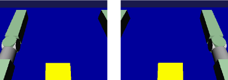
Try displaying the saved images with an appropriate image viewer. The saved images simulate the camera images corresponding to the robot’s left and right eyes. Examples of each are shown below.
This shows that camera image simulation is working and that the controller can obtain them.
Note
Some image viewers have a function to automatically detect file updates and update the display. For example, the image viewer “gThumb” that runs on Linux has this function. (On Ubuntu, you can install it with “apt-get install gthumb”.) Using such a viewer, you can see how camera images are updated as the simulation progresses.
In addition to the regular Camera type targeted this time, by specifying COLOR_DEPTH for format in the Camera node in the model file, you can make it a RangeCamera that can also acquire distance image data. In that case, you can access distance image data in the same way as image data, so if you’re interested, try modifying the SR1 model and sample controller.
Sample Controller Implementation Details
The source code for CameraSampleController is shown below:
#include <cnoid/SimpleController>
#include <cnoid/Camera>

using namespace cnoid;

class CameraSampleController : public SimpleController
{
    DeviceList<Camera> cameras;
    double timeCounter;
    double timeStep;
    std::ostream* os;

public:
    virtual bool initialize(SimpleControllerIO* io) override
    {
        os = &io->os();

        cameras << io->body()->devices();

        for(size_t i=0; i < cameras.size(); ++i){
            Device* camera = cameras[i];
            io->enableInput(camera);
            *os << "Device type: " << camera->typeName()
                << ", id: " << camera->id()
                << ", name: " << camera->name() << std::endl;
        }

        timeCounter = 0.0;
        timeStep = io->timeStep();

        return true;
    }

    virtual bool control() override
    {
        timeCounter += timeStep;
        if(timeCounter >= 1.0){
            for(size_t i=0; i < cameras.size(); ++i){
                Camera* camera = cameras[i];
                std::string filename = camera->name() + ".png";
                camera->constImage().save(filename);
                *os << "The image of " << camera->name()
                    << " has been saved to \"" << filename << "\"." << std::endl;
            }
            timeCounter = 0.0;
        }
        return false;
    }
};

CNOID_IMPLEMENT_SIMPLE_CONTROLLER_FACTORY(CameraSampleController)
For using Camera devices,
#include <cnoid/Camera>
includes the Camera class definition, and
DeviceList<Camera> cameras;
with
cameras << io->body()->devices();
obtains all Camera devices that the robot model has.
For the Camera devices obtained this way, in the for loop in the initialize function
io->enableInput(camera);
enables input from each camera. It also outputs camera information as text messages.
In the control function
camera->constImage().save(filename);
outputs the camera’s image data to a file. Here we use the constImage() function because we don’t edit the acquired image data.
The above covers the parts related to Camera devices. For other parts, there are many commonalities with Controller Implementation, so please refer to that explanation.